
Materials Today Advances ( IF 7.579 ) Pub Date : 2021-09-01 , DOI: 10.1016/j.mtadv.2021.100161
L.M.G. Silva , G.N. Leocádio , R.F.B. de Souza , J.C. Mierzwa , A. Duong , E.C. Venancio , A.O. Neto
 |
应用电喷雾技术的性能来获得用于质子交换膜燃料电池的气体扩散层 (GDL)。共聚焦显微镜证实,聚四氟乙烯 (PTFE) 浸渍到骨架中,形成均匀分布在基材上的微观尺寸分散层。PTFE层通过红外光谱和热重分析表征。在这项工作中,我们证明了使用电喷雾制备的 GDL 增加了 H 2 /O 2的最大功率由于更好的分布特性疏水涂层对气体扩散具有低阻抗,因此燃料电池减少了约 10%,并降低了电极的扩散损失。因此,我们的方法有望通过生产扩散层来开发燃料电池。
New approach by electrospray technique to prepare a gas diffusion layer for the proton exchange membrane fuel cell anode
Author links open overlay panelL.M.G.SilvaacdG.N.LeocádiobR.F.B.de SouzaaJ.C.MierzwabA.DuongdE.C.VenanciocA.O.Netoa
Show more
Add to Mendeley
Share
Cite
https://doi.org/10.1016/j.mtadv.2021.100161Get rights and content
Under a Creative Commons license
Open access
Abstract
The performance of the electrospray technique was applied to obtain a gas diffusion layer (GDL) for a proton exchange membrane fuel cell. It was confirmed by confocal microscopy that polytetrafluorethylene (PTFE) was impregnated into the backbone, forming a dispersed layer of microscopic size homogeneously distributed over the substrate. The PTFE layer was characterized by infrared spectroscopy and thermogravimetric analysis. In this work, we demonstrated that the use of the GDL prepared by electrospray increases the maximum power of the H2/O2 fuel cell by about 10% and decreases the diffusion loss of the electrode owing to a better distribution characteristic hydrophobic coating with low impedance to gas diffusion. Thus, our method is promising for the development of fuel cells by the production of diffusion layers.
Graphical abstract
Keywords
Gas diffusion layer
PEMFC
Electrospray
1. Introduction
The proton exchange membrane fuel cell (PEMFC) has attracted increasing attention in recent years owing to its high efficiency, low noise, and zero carbon emissions. PEMFC systems are considered the most promising candidates owing to their high gravimetric energy density, which is also ascribed to their application flexibility arrangement [1,2]. One of the most important components of the PEMFC is the gas diffusion layers (GDLs) [[1], [2], [3]], which function primarily as i) a gas diffuser, ii) a current collector, and iii) a physical carrier, thereby determining catalyst utilization and overall performance. It also allows the water in the gas phase to reach the membrane and water in the liquid phase to exit the catalyst layer. A GDL is moistureproof to prevent water flooding and increases the transport of reagents to the catalyst active sites [1]. Currently, the most common GDLs are made of a carbon paper and carbon cloth, both with geometric structures [2].
As aforementioned, to obtain a GDL support by the classic methods is necessary to prepare a gas diffusion electrode, which consists of the application of PTFE to an electrocatalyst paste on a moisture-resistant carbon paper substrate or carbon cloth. Then the incorporation of PTFE in the electrocatalyst layer has two functions: (a) as a cohesive layer, to connect the electrocatalyst to a high surface area; and (b) impart some hydrophobic character to the electrocatalyst layer [3].
The influence regarding the amount of PTFE and the coating mode is investigated in the literature [[4], [5], [6]], and it was discovered that there is an optimum quantity of them, which might jeopardize in a good way the performance of the cell in the maximum expected [7]. In addition, increasing the PTFE content by more than a threshold value may also detain the permeability and diffusivity of the GDL to some extent, for which the increased hydrophobicity of the GDL will no longer be useful.
Recent studies indicate the use of treatment methods such as emerging or spraying the carbon support as a form of impregnation of the hydrophobic layer [8,9]. These methods provide a smaller amount of PTFE particles in the cloth, resulting in a non-homogeneous PTFE distribution. This poor distribution of PTFE may also be responsible for the degradation of the GDL [10]. This work deals with the preparation of the GDL impregnating the electrode backbone with PTFE by electrospray, ensuring better coverage and distribution of the coating, aiming at an increase in the performance of the fuel cell.
2. Experimental
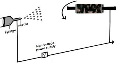
PTFE 60wt% dispersion in H2O was held in a syringe. An electrospinning machine was prepared for electrospray, a flat carbon cloth was placed in a rotating collector (work distance of 10 cm and speed 750 rpm) from the tip of the needle (0.5 mm inner diameter). The feeding rate of 2.0 mL h−1 for the solution was controlled by using a syringe pump, and the voltage applied was 10 kV. The PTFE electrospray film was impregnated onto the carbon cloth for at least 40 min (20 °C and ~45% relative humidity). After the carbon cloth impregnated was weighed and the proportion of the PTFE on the substrate is controlled to 20% (wt%). For comparison, a standard GDL was prepared by Giorgi's method [11]. A homogeneous suspension was prepared by mixing carbon (2 mg cm−1) with an appropriate amount of PTFE dispersion (20% wt%) and stirring in an ultrasonic bath at room temperature for 25 min. The suspension was deposited by the doctor blade method onto a carbon cloth. The layer was dried in air at 120 °C for 1 h, followed by thermal treatment at 280 °C for 30 min to remove the dispersion agent contained in PTFE, and finally sintered at 350 °C for 30 min.
The electrospray GDL was morphologically characterized using an Olympus LEXT OLS4100 laser scanning digital microscope non-contact three-dimensional observations and measurements of surface features at 10-nm resolutions. The PTFE impregnated in the carbon cloth was confirmed using an fourier transform infrared spectroscopy (FTIR) performed in an attenuated total reflectance (ATR) accessory (MIRacle with a ZnSe Crystal Plate Pike) installed on a Nicolet 6700 FTIR spectrometer equipped with an mercury-cadmium-telluride IR infrared detector (MCT) detector cooled with liquid N2. And the PTFE load confirmed by thermogravimetric analysis was performed on a SETARAM LABSYS. The samples were heated up under an inert atmosphere (N2) from 25 to 900 °C at a constant rate of 10 °C per minute.
Contact angle measurements were performed as per to the methodology international organization for standardization (ISO) 15989/2004 using a goniometric (KINO-SL150E) as displayed in the système international (SI) file. For the contact angle measurements was used water droplets of 2.0 μL of deionized water were placed on the surface of the samples. The results were obtained, and the digital image was used to determine the contact angle. The measurements were performed on a minimum of five different samples of each support, measured ten times for each sample, and the average values were registered.
PEMFC tests were carried out using Pt/C BASF (20 wt%) as the anode with 1mgPt cm−2 deposited in both types of substrates with 5 cm2 (carbon cloth with a diffusion layer and PTFE-impregnated carbon cloth by electrospray) by painting in the form of a homogeneous dispersion prepared using the Nafion solution (5 wt%, Aldrich). For the cathode with 1mgPt cm−2 deposited in on a carbon cloth with the diffusion layer (5 cm2) by painting in the form of a homogeneous dispersion prepared using the Nafion solution (5 wt%, Aldrich) as an anode. After the preparation, the electrodes were hot-pressed on both sides of a Nafion 117 membrane at 125 °C for 3 min under a pressure of 247 kgf cm−2. The fuel cell operation temperature was set to 80 °C in a cell, 85 °C for the hydrogen humidifier, and 85 °C for the oxygen humidifier, with a flow rate of 300 mL min−1 H2 and 200 mL min−1 O2 [12]. The curves were obtained in triplicates by using an Autolab potentiostat working in a potentiostatic mode, after the experiments, arithmetic measurements of the curves obtained were carried out. The curves were obtained in triplicates, and the results were reproducible, that is, with differences less than 5%.
3. Results and discussion
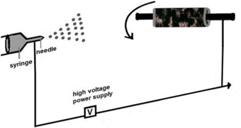
Fig. 1 shows the confocal images of the carbon cloth before (Fig. 1A) and after the PTFE deposition for electrospray (electrospray GDL), and it is possible to see the carbon fibers covered by small formations of PTFE spaced out over the entire length of the cloth (Fig. 1B). The magnification image (Fig. 1C) shows that the PTFE formations are connected by agglomerated microspheres which can promote superhydrophobic points on the substrate according to Burkarter et al. [13].
Fig. 1. Confocal images of the carbon cloth before and after PTFE electrospray deposition. (A) Bare carbon cloth 400 μm, (B) Electrospray GDL 400 μm, (C) Electrospray GDL 50 μm.
The incorporation of the PTFE on the surface of the carbon cloth is confirmed by ATR-FTIR (Fig. 2A). The band at 1145 and 1213 cm−1 corresponding to symmetrical and asymmetrical stretching of CF2, respectively [14], are characteristics of PTFE and were not present in the bare carbon cloth. The presence of PTFE is also confirmed by the thermogravimetric curves where the following two steps are observed for PTFE-impregnated carbon cloth: i) the gradual loss of adsorbed water from 25 to 200 °C; and ii) the degradation of PTFE particles from 470 to 560 °C [15]. The thermal degradation of PTFE indicated the mass loss of 23% confirming the amount of polymer impregnated on the carbon substrate by electrospraying.
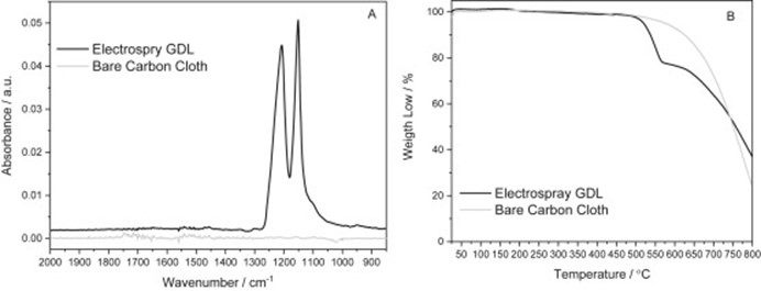
Fig. 2. Comparison of bare and PTFE-impregnated carbon cloths. (A) FTIR spectra and (B) thermogravimetric analysis (TG) curves.
To observe the hydrophobicity of the GDL in comparison with the commonly used, the water contact angle was measured to get information regarding the performance of the cell. This is directly associated with the improvement in the permeability and diffusivity of some desirable species for this type of GDL application (Fig. 3). The contact angles measured are shown in the Table. Anova contact angle sample (ANOVA) for an electrospray GDL is 112.58° ± 5.09, for a standard GDL 131.71° ± 4.90, and for a bare carbon cloth, the water was absorbed. When compared by ANOVA, the average contact angle (Table 1) was significantly different with a 5% significance level considered p-value = 0.00.
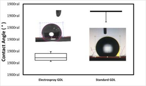
Fig. 3. Contact angle results of GDL supports.
Table 1. ANOVA contact angle results.
|
Contact Angle |
ANOVA |
||||
|
Sample |
Contact angle (°) |
Samples |
F calc |
F crit |
p-value |
| Electrospray GDL | 112.58 ± 5.09 | A + B | 157,90 | 5,32 | 0,00 |
| Standard GDL | 131.71 ± 4.90 | ||||
The 17% smaller contact angle measured for carbon the cloth impregnated with PTFE can be attributed to the different morphology seen in Fig. 1C where the presence of particles with globular shape and the formation of small channels are observed [3,16,17].
The polarization and power density curves for catalyst layers with two different PTFE impregnation methods working in the H2/O2 gas feed mode are shown in Fig. 4. The performances of the new way of depositing PTFE in the catalyst layers were evaluated by comparing it with the conventional form of PTFE impregnation. Very close values of power densities were obtained amounting to 184 mWcm−2 for the electrospray GDL and 171 mWcm−2 for the standard GDL derived. However, the V/i curves indicate that the performance of both materials is similar till reaching the diffusional loss region of the standard GDL.
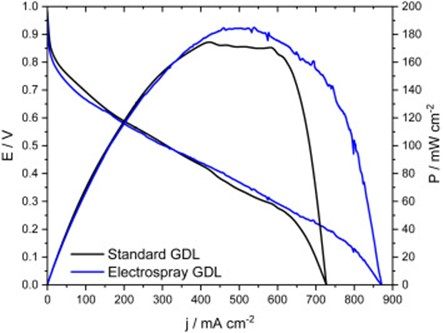
Fig. 4. Polarization and power density curves of the H2/O2 fuel cell at Pt/C.
The current density of the electrospray GDL at the anode reached 870 mA/cm−2, and this value was higher than the standard GDL (730 mA/cm−2). In the range of 0.9 V–0.6 V, in the region of loss by activation, the GDL standard is larger, which may be some difference in the capacitance of the substrate, or just some experimental error, at the point of the greatest difference between these currents measured between the GDL in this region it is less than 3%. In the greater range of 0.9 to 0.3 V, the currents are too close to discuss any superiority. This difference is observed mainly in the region of mass transport control (between 0.0 and 0.3 V) of the curve. It can be explained by the structural and diffusional alteration provided by the electrospray impregnation method. The electrospray GDL could also allow greater fuel access to activate platinum sites.
4. Conclusion
The new approach to impregnating PTFE in the carbon cloth to make the GDL by electrospray proves to be advantageous. The morphological characterization showed the incorporation and good distribution of PTFE on the surface, corroborated with these results, or the FTIR presented characteristic bands at 635, 1145, and 1213 cm−1 indicative of CF2. The thermal analysis showed the decomposition regions of the different components of the PTFE dispersion, with a region II (486 and 565 °C) attributed to PEO and a region III (565 and 837 °C) attributed to PTFE. From the analysis of contact angles, it was possible to observe a lower hydrophobicity for the electrospray GDL than that for the standard GDL. This difference in hydrophobicity can be verified by the ANOVA method, when the mean contact angle was significantly different, with a significance level of 5% considered p = 0.00. The change in observed morphological structure in the PTFE deposited by the electrospray method changed the diffusion pathways in the GDL, decreasing the diffusion losses in the polarization curves, thus being able to extract more current than the PEMFC. In future, the electrospray technique could be used for the preparation of a new catalytic layer for applications in PEMFC.
Credit author statement
L.M.G Silva: Preparation and execution of electrochemical characterization experiments.
G.N Leocádiob: Preparation and execution of electrospray experiments.
R.F.B. de Souza: Preparation, execution, and discussion of experiments; preparation, creation, and/or presentation of the published work, specifically writing the initial draft; planning and execution research.
JC Mierzwab: Preparation, creation, and presentation of the published work writing the finally draft.
A. Duong: Preparation, creation, and presentation of the published work writing the finally draft.
E.C. Venancio: Preparation, creation, and presentation of the published work writing the finally draft.
Almir Oliveira Neto: Management and coordination responsibility for the research activity planning and execution; oversight and leadership responsibility for the research activity planning and execution.
Declaration of competing interest
The authors declare that they have no known competing financial interests or personal relationships that could have appeared to influence the work reported in this article.
Acknowledgments
The authors thank CAPES (88882.315566/2019–01), FAPESP (2017/11937-4), CNPq (302709/2020-7), the Natural Sciences and Engineering Research Council of Canada (RGPIN-2015-06425) for the fellowships and the financial support this work.
 艾邦氢能产业链通讯录,目前有2200人加入,如亿华通、清极能源、氢蓝时代、雄韬、氢牛、氢璞、爱德曼、氢晨、喜马拉雅、明天氢能、康明斯、新源动力、巴拉德、现代汽车、神力科技、中船712等等,可以按照标签筛选,请点击下方关键词试试
资料下载:
艾邦氢能产业链通讯录,目前有2200人加入,如亿华通、清极能源、氢蓝时代、雄韬、氢牛、氢璞、爱德曼、氢晨、喜马拉雅、明天氢能、康明斯、新源动力、巴拉德、现代汽车、神力科技、中船712等等,可以按照标签筛选,请点击下方关键词试试
资料下载: